

Image Segmentation (photutils.segmentation)#
Introduction#
Photutils includes general-use functions to detect sources (both point-like and extended) in an image using a process called image segmentation. After detecting sources using image segmentation, we can then measure their photometry, centroids, and shape properties.
Source Extraction Using Image Segmentation#
Image segmentation is a process of assigning a label to every pixel in an image such that pixels with the same label are part of the same source. Detected sources must have a minimum number of connected pixels that are each greater than a specified threshold value in an image. The threshold level is usually defined as some multiple of the background noise (sigma level) above the background. The image is usually filtered before thresholding to smooth the noise and maximize the detectability of objects with a shape similar to the filter kernel.
Let’s start by making a synthetic image provided by the photutils.datasets module:
>>> from photutils.datasets import make_100gaussians_image
>>> data = make_100gaussians_image()
Next, we need to subtract the background from the image. In this
example, we’ll use the Background2D class
to produce a background and background noise image:
>>> from photutils.background import Background2D, MedianBackground
>>> bkg_estimator = MedianBackground()
>>> bkg = Background2D(data, (50, 50), filter_size=(3, 3),
...                    bkg_estimator=bkg_estimator)
>>> data -= bkg.background  # subtract the background
After subtracting the background, we need to define the detection threshold. In this example, we’ll define a 2D detection threshold image using the background RMS image. We set the threshold at the 1.5-sigma (per pixel) noise level:
>>> threshold = 1.5 * bkg.background_rms
Next, let’s convolve the data with a 2D Gaussian kernel with a FWHM of 3 pixels:
>>> from astropy.convolution import convolve
>>> from photutils.segmentation import make_2dgaussian_kernel
>>> kernel = make_2dgaussian_kernel(3.0, size=5)  # FWHM = 3.0
>>> convolved_data = convolve(data, kernel)
Now we are ready to detect the sources in the background-subtracted
convolved image. Let’s find sources that have 10 connected pixels that
are each greater than the corresponding pixel-wise threshold level
defined above (i.e., 1.5 sigma per pixel above the background noise).
Note that by default “connected pixels” means “8-connected” pixels,
where pixels touch along their edges or corners. One can also use
“4-connected” pixels that touch only along their edges by setting
connectivity=4:
>>> from photutils.segmentation import detect_sources
>>> segment_map = detect_sources(convolved_data, threshold, n_pixels=10)
>>> print(segment_map)
<photutils.segmentation.core.SegmentationImage>
shape: (300, 500)
n_labels: 86
labels: [ 1  2  3  4  5 ... 82 83 84 85 86]
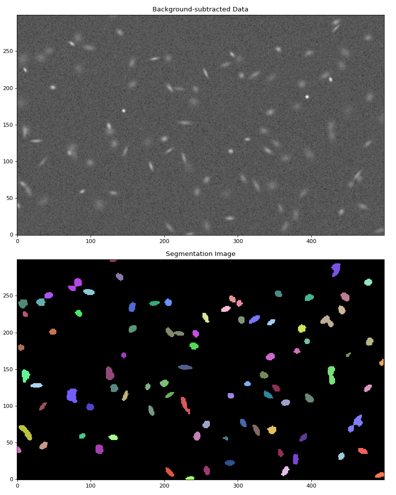
The result is a SegmentationImage
object with the same shape as the data, where detected sources are
labeled by different positive integer values. Background pixels
(non-sources) always have a value of zero. Because the segmentation
image is generated using image thresholding, the source segments
represent the isophotal footprints of each source.
Let’s plot both the background-subtracted image and the segmentation image showing the detected sources:
>>> import numpy as np
>>> import matplotlib.pyplot as plt
>>> from astropy.visualization import simple_norm
>>> norm = simple_norm(data, 'sqrt', percent=99.5)
>>> fig, (ax1, ax2) = plt.subplots(2, 1, figsize=(10, 12.5))
>>> ax1.imshow(data, norm=norm, origin='lower')
>>> ax1.set_title('Background-subtracted Data')
>>> segment_map.imshow(ax=ax2)
>>> ax2.set_title('Segmentation Image')
(Source code, png, hires.png, pdf, svg)


Source Deblending#
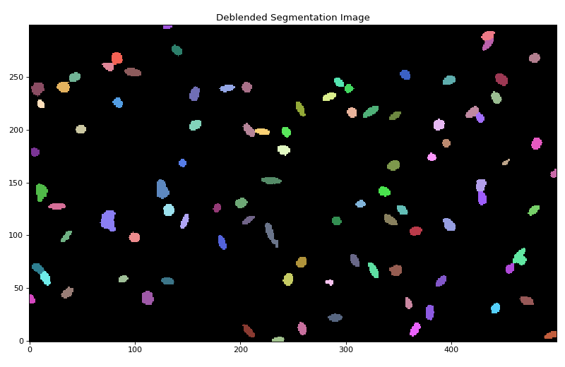
In the example above, overlapping sources are detected as single
sources. Separating those sources requires a deblending procedure,
such as a multi-thresholding technique used by SourceExtractor.
Photutils provides a deblend_sources()
function that deblends sources using a combination
of multi-thresholding and watershed segmentation. Note
that in order to deblend sources, they must be separated enough that ere
this a saddle point between them.
The amount of deblending can be controlled with the two
deblend_sources() keywords n_levels
and contrast. n_levels is the number of multi-thresholding
levels to use. contrast is the fraction of the total source flux
that a local peak must have to be considered as a separate object.
Here’s a simple example of source deblending:
>>> from photutils.segmentation import deblend_sources
>>> segment_map2 = deblend_sources(convolved_data, segment_map,
...                                n_pixels=10, n_levels=32, contrast=0.001,
...                                progress_bar=False)
where segment_map is the
SegmentationImage that was
generated by detect_sources(). Note
that the convolved_data and n_pixels input values should
match those used in detect_sources()
to generate segment_map. The result is a new
SegmentationImage object containing the
deblended segmentation image:
(Source code, png, hires.png, pdf, svg)


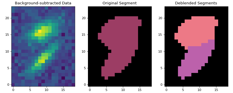
Let’s plot one of the deblended sources:
(Source code, png, hires.png, pdf, svg)


SourceFinder#
The SourceFinder class
is a convenience class that combines the functionality
of detect_sources and
deblend_sources. After defining the object
with the desired detection and deblending parameters, you call it with
the background-subtracted (convolved) image and threshold:
>>> from photutils.segmentation import SourceFinder
>>> finder = SourceFinder(n_pixels=10, progress_bar=False)
>>> segment_map = finder(convolved_data, threshold)
>>> print(segment_map)
<photutils.segmentation.core.SegmentationImage>
shape: (300, 500)
n_labels: 93
labels: [ 1  2  3  4  5 ... 89 90 91 92 93]
Modifying a Segmentation Image#
The SegmentationImage object provides
several methods that can be used to modify itself (e.g.,
combining labels, removing labels, removing border segments) prior to
measuring source photometry and other source properties, including:
relabel_consecutive(): Reassign the label numbers consecutively, such that there are no missing label numbers.reassign_labels(): Reassign one or more label numbers.keep_labels(): Keep only the specified labels.remove_labels(): Remove one or more labels.remove_border_labels(): Remove labeled segments near the image border.remove_masked_labels(): Remove labeled segments located within a masked region.
Here’s a simple example of removing border labels and relabeling the result:
>>> segment_map3 = segment_map.copy()
>>> segment_map3.remove_border_labels(border_width=10, relabel=True)
>>> print(segment_map3)
<photutils.segmentation.core.SegmentationImage>
shape: (300, 500)
n_labels: 79
labels: [ 1  2  3  4  5 ... 75 76 77 78 79]
Source Masks#
The make_source_mask()
method can be used to create a boolean source mask from a segmentation
image. The source mask can be used, for example, to mask sources
when estimating the background level. The source mask can optionally
be dilated using the size or footprint keyword to mask a
larger area around each source. Dilating the source mask is useful for
excluding the faint wings of sources when estimating the background:
>>> mask = segment_map.make_source_mask()
>>> dilated_mask = segment_map.make_source_mask(size=11)
A circular footprint can also be used to dilate the source mask:
>>> from photutils.utils import circular_footprint
>>> footprint = circular_footprint(radius=5)
>>> dilated_mask2 = segment_map.make_source_mask(footprint=footprint)
Note that using a square footprint (via the size keyword) is much
faster than using other shapes (e.g., a circular footprint).
Polygons and Regions#
The SegmentationImage class
provides several methods for converting source segments into
polygon representations and regions objects. These are useful
for visualization and for exporting source segments to other tools.
Note that these methods require the rasterio, shapely, and/or
regions optional packages.
The polygons property
returns a list of Shapely polygon objects representing each source
segment:
>>> polygons = segment_map.polygons
The to_patches() method
returns a list of PathPatch objects for the source
segments, which can be overlaid on plots:
>>> patches = segment_map.to_patches(edgecolor='white', lw=1.5)
For convenience, the
plot_patches() method
will plot these patches directly on an existing matplotlib axes:
>>> patches = segment_map.plot_patches(edgecolor='white', lw=1.5)
For working with individual labels, the
get_polygon(),
get_polygons(),
get_patch(),
get_patches(),
get_region(), and
get_regions() methods
are significantly faster than the bulk properties when only a subset of
labels is needed:
>>> polygon = segment_map.get_polygon(1)
>>> patch = segment_map.get_patch(1, edgecolor='red', lw=2)
>>> region = segment_map.get_region(1)
Here’s an example showing the source polygons overlaid on both the segmentation image and the science image:
(Source code, png, hires.png, pdf, svg)


To convert the source segments to regions
PolygonPixelRegion objects, use the
to_regions() method:
>>> regions = segment_map.to_regions()
Segment Objects#
The SegmentationImage class provides
Segment objects that encapsulate
individual labeled regions. Each Segment
contains the label number, bounding-box slices, bounding box, area, and
(optionally) the Shapely polygon outline.
The segments property
returns a list of Segment objects for all
labels:
>>> segments = segment_map.segments
>>> segments[0]
<photutils.segmentation.core.Segment>
label: 1
slices: (slice(0, 5, None), slice(230, 242, None))
area: 47
For working with individual labels, the
get_segment() and
get_segments() methods
are significantly faster than the bulk segments property when only a
subset of labels is needed:
>>> segment = segment_map.get_segment(1)
>>> print(segment.label, segment.area)
1 47

>>> segments = segment_map.get_segments([1, 5, 10])
>>> [segment.label for segment in segments]
[np.int32(1), np.int32(5), np.int32(10)]
A Segment can provide cutout arrays
of the segment data and of arbitrary data arrays via its
data property and
make_cutout() method:
>>> segment = segment_map.get_segment(1)
>>> segment_cutout = segment.data  # labeled region, others set to 0
>>> data_cutout = segment.make_cutout(data)  # science data cutout
Photometry, Centroids, and Shape Properties#
The SourceCatalog class is the primary
tool for measuring the photometry, centroids, and shape/morphological
properties of sources defined in a segmentation image. In its most
basic form, it takes as input the (background-subtracted) image and
the segmentation image. Usually the convolved image is also input,
from which the source centroids and shape/morphological properties are
measured (if not input, the unconvolved image is used instead).
Let’s continue our example from above and measure the properties of the detected sources:
>>> from photutils.segmentation import SourceCatalog
>>> cat = SourceCatalog(data, segment_map, convolved_data=convolved_data)
>>> print(cat)
<photutils.segmentation.catalog.SourceCatalog>
Length: 93
labels: [ 1  2  3  4  5 ... 89 90 91 92 93]
The source properties can be accessed using
SourceCatalog attributes or
output to an Astropy QTable using the
to_table() method. Please
see SourceCatalog for the many
properties that can be calculated for each source. More properties are
likely to be added in the future.
Here we’ll use the
to_table() method to
generate a QTable of source properties. Each row in the
table represents a source. The columns represent the calculated source
properties. The label column corresponds to the label value in the
input segmentation image. Note that only a small subset of the source
properties are shown below:
>>> tbl = cat.to_table()
>>> tbl['x_centroid'].info.format = '.2f'  # optional format
>>> tbl['y_centroid'].info.format = '.2f'
>>> tbl['kron_flux'].info.format = '.2f'
>>> print(tbl)
label x_centroid y_centroid ... segment_flux_err kron_flux kron_flux_err
                            ...
----- ---------- ---------- ... ---------------- --------- -------------
    1     235.38       1.44 ...              nan    490.35           nan
    2     493.78       5.84 ...              nan    489.37           nan
    3     207.29      10.26 ...              nan    694.24           nan
    4     364.87      11.13 ...              nan    681.20           nan
    5     257.85      12.18 ...              nan    748.18           nan
  ...        ...        ... ...              ...       ...           ...
   89     292.77     244.93 ...              nan    792.63           nan
   90      32.66     241.24 ...              nan    930.77           nan
   91      42.60     249.43 ...              nan    580.54           nan
   92     433.80     280.74 ...              nan    663.44           nan
   93     434.03     288.88 ...              nan    879.64           nan
Length = 93 rows
The error columns are NaN because we did not input an error array (see the Photometric Errors section below).
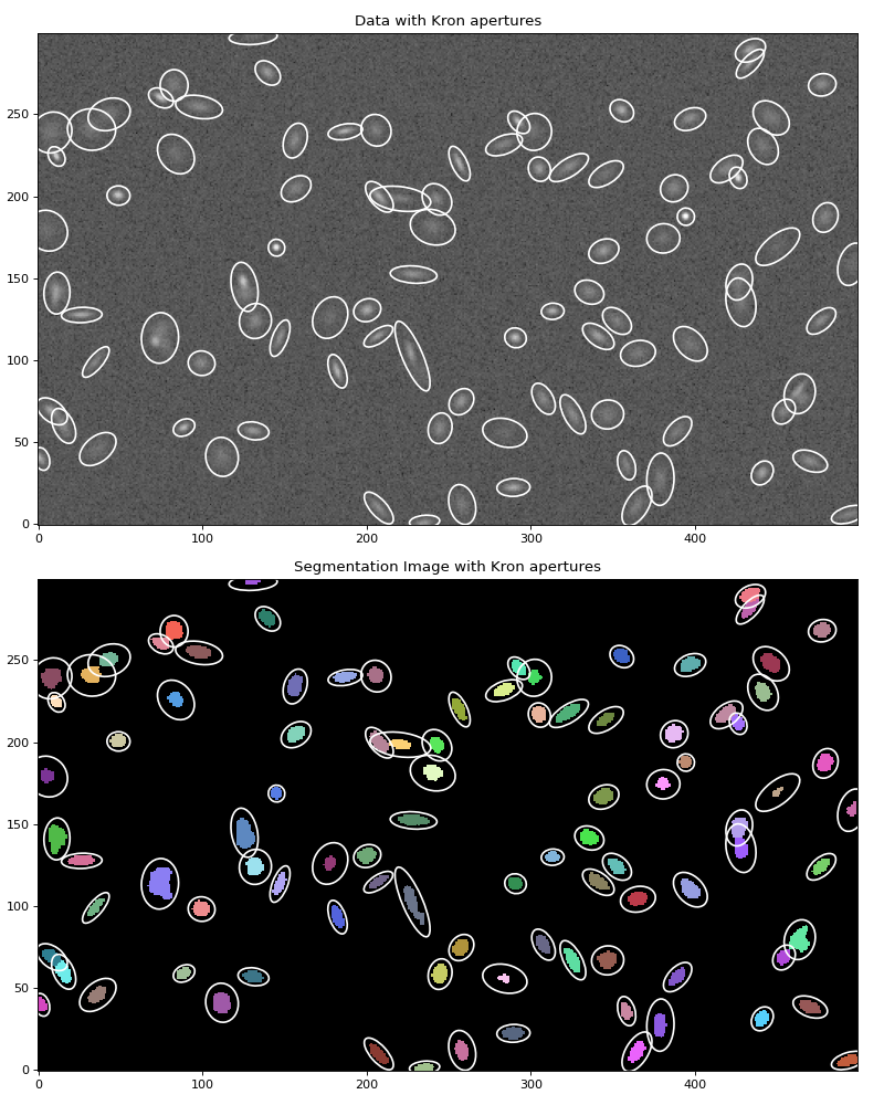
Let’s plot the calculated elliptical Kron apertures (based on the shapes of each source) on the data:
>>> import numpy as np
>>> import matplotlib.pyplot as plt
>>> from astropy.visualization import simple_norm
>>> norm = simple_norm(data, 'sqrt', percent=99.5)
>>> fig, (ax1, ax2) = plt.subplots(2, 1, figsize=(10, 12.5))
>>> ax1.imshow(data, norm=norm, origin='lower')
>>> ax1.set_title('Data')
>>> segment_map.imshow(ax=ax2)
>>> ax2.set_title('Segmentation Image')
>>> cat.plot_kron_apertures(ax=ax1, color='white', lw=1.5)
>>> cat.plot_kron_apertures(ax=ax2, color='white', lw=1.5)
(Source code, png, hires.png, pdf, svg)


We can also create a SourceCatalog object
containing only a specific subset of sources, defined by their
label numbers in the segmentation image:
>>> cat = SourceCatalog(data, segment_map, convolved_data=convolved_data)
>>> labels = [1, 5, 20, 50, 75, 80]
>>> cat_subset = cat.select_labels(labels)
>>> tbl2 = cat_subset.to_table()
>>> tbl2['x_centroid'].info.format = '.2f'  # optional format
>>> tbl2['y_centroid'].info.format = '.2f'
>>> tbl2['kron_flux'].info.format = '.2f'
>>> print(tbl2)
label x_centroid y_centroid ... segment_flux_err kron_flux kron_flux_err
                            ...
----- ---------- ---------- ... ---------------- --------- -------------
    1     235.38       1.44 ...              nan    490.35           nan
    5     257.85      12.18 ...              nan    748.18           nan
   20     347.17      66.45 ...              nan    855.34           nan
   50     381.02     174.67 ...              nan    438.55           nan
   75      74.44     259.78 ...              nan    876.02           nan
   80      14.93      60.06 ...              nan    878.52           nan
By default, the to_table()
includes only a small subset of source properties. The output table
properties can be customized in the QTable using the
columns keyword:
>>> cat = SourceCatalog(data, segment_map, convolved_data=convolved_data)
>>> labels = [1, 5, 20, 50, 75, 80]
>>> cat_subset = cat.select_labels(labels)
>>> columns = ['label', 'x_centroid', 'y_centroid', 'area', 'segment_flux']
>>> tbl3 = cat_subset.to_table(columns=columns)
>>> tbl3['x_centroid'].info.format = '.4f'  # optional format
>>> tbl3['y_centroid'].info.format = '.4f'
>>> tbl3['segment_flux'].info.format = '.4f'
>>> print(tbl3)
label x_centroid y_centroid  area segment_flux
                             pix2
----- ---------- ---------- ----- ------------
    1   235.3827     1.4439  47.0     433.3546
    5   257.8501    12.1764  84.0     489.9653
   20   347.1743    66.4462 103.0     625.9668
   50   381.0186   174.6745  50.0     249.0170
   75    74.4448   259.7843  66.0     836.4803
   80    14.9296    60.0641  87.0     666.6014
A WCS transformation can also be input to
SourceCatalog via the wcs keyword,
in which case the sky coordinates of the source centroids can be
calculated.
Background Properties#
Like with aperture_photometry(), the data
array that is input to SourceCatalog
should be background subtracted. If you input the background image
that was subtracted from the data into the background keyword
of SourceCatalog, the background
properties for each source will also be calculated:
>>> cat = SourceCatalog(data, segment_map, background=bkg.background)
>>> labels = [1, 5, 20, 50, 75, 80]
>>> cat_subset = cat.select_labels(labels)
>>> columns = ['label', 'background_centroid', 'background_mean',
...            'background_sum']
>>> tbl4 = cat_subset.to_table(columns=columns)
>>> tbl4['background_centroid'].info.format = '{:.10f}'  # optional format
>>> tbl4['background_mean'].info.format = '{:.10f}'
>>> tbl4['background_sum'].info.format = '{:.10f}'
>>> print(tbl4)
label background_centroid background_mean background_sum
----- ------------------- --------------- --------------
    1        5.1950691156    5.1952758684 244.1779658169
    5        5.2065578767    5.2065437428 437.3496743914
   20        5.2185224938    5.2182859243 537.4834502022
   50        5.2278578177    5.2277566101 261.3878305059
   75        5.2200812077    5.2203644550 344.5440540277
   80        5.2177773524    5.2174773951 453.9205333733
Photometric Errors#
SourceCatalog requires inputting a
total error array, i.e., the background-only error plus Poisson noise
due to individual sources. The calc_total_error()
function can be used to calculate the total error array from a
background-only error array and an effective gain.
The effective_gain, which is the ratio of counts (electrons or
photons) to the units of the data, is used to include the Poisson noise
from the sources. effective_gain can either be a scalar value or a
2D image with the same shape as the data. A 2D effective gain image
is useful for mosaic images that have variable depths (i.e., exposure
times) across the field. For example, one should use an exposure-time
map as the effective_gain for a variable depth mosaic image in
count-rate units.
Let’s assume our synthetic data is in units of electrons per
second. In that case, the effective_gain should be the
exposure time (here we set it to 500 seconds). Here we use
calc_total_error() to calculate the total error
and input it into the SourceCatalog
class. When a total error is input, the
segment_flux_err and
kron_flux_err properties are
calculated. segment_flux
and segment_flux_err are the
instrumental flux and propagated flux error within the source segments:
>>> from photutils.utils import calc_total_error
>>> effective_gain = 500.0
>>> error = calc_total_error(data, bkg.background_rms, effective_gain)
>>> cat = SourceCatalog(data, segment_map, error=error)
>>> labels = [1, 5, 20, 50, 75, 80]
>>> cat_subset = cat.select_labels(labels)  # select a subset of objects
>>> columns = ['label', 'x_centroid', 'y_centroid', 'segment_flux',
...            'segment_flux_err']
>>> tbl5 = cat_subset.to_table(columns=columns)
>>> tbl5['x_centroid'].info.format = '{:.4f}'  # optional format
>>> tbl5['y_centroid'].info.format = '{:.4f}'
>>> tbl5['segment_flux'].info.format = '{:.4f}'
>>> tbl5['segment_flux_err'].info.format = '{:.4f}'
>>> for col in tbl5.colnames:
...     tbl5[col].info.format = '%.8g'  # for consistent table output
>>> print(tbl5)
label x_centroid y_centroid segment_flux segment_flux_err
----- --------- --------- ------------ ----------------
    1 235.24302 1.1928271    433.35463        14.167067
    5 257.82267 12.228232    489.96534        18.998371
   20 347.15384 66.417567    625.96683        22.475065
   50 380.94448 174.57181    249.01701        15.261334
   75 74.413068 259.76066     836.4803        17.193721
   80 14.920217 60.024006     666.6014        19.605394
Pixel Masking#
Pixels can be completely ignored/excluded (e.g., bad pixels) when
measuring the source properties by providing a boolean mask image
via the mask keyword (True pixel values are masked) to the
SourceCatalog class. Note that
non-finite data values (NaN and inf) are automatically masked.
Filtering#
SourceExtractor’s centroid and morphological parameters are
always calculated from a convolved, or filtered, “detection” image
(convolved_data), i.e., the image used to define the segmentation
image. The usual downside of the filtering is the sources will be
made more circular than they actually are. If you wish to reproduce
SourceExtractor centroid and morphology results, then input the
convolved_data. If convolved_data is None, then the unfiltered
data will be used for the source centroid and morphological
parameters. Note that photometry is always performed on the unfiltered
data.
Dual-Image Mode (Detection Catalog)#
In many astronomical workflows, source detection and deblending
are performed on one image (e.g., a deep detection image or
coadd) while photometry is measured on a different image (e.g.,
a single-band image). The detection_catalog keyword of
SourceCatalog enables this dual-image
mode.
When detection_catalog is input, the source centroids and
morphological/shape properties are taken from the detection
catalog, while photometry is measured on the input data. For
circular-aperture and Kron photometry, the aperture centers are based on
the centroids from the detection catalog. For Kron photometry, the Kron
apertures are based on the shape properties from the detection catalog.
The wcs, aperture_mask_method, and kron_params keywords
are inherited from the detection_catalog and are therefore ignored
when detection_catalog is input. Note that the segmentation image
used to create the detection catalog must be the same one input to the
measurement catalog:
>>> det_cat = SourceCatalog(data, segment_map,
...                         convolved_data=convolved_data)
>>> measurement_cat = SourceCatalog(data, segment_map,
...                                 detection_catalog=det_cat)
In this example, measurement_cat uses the centroids and shape
properties (and Kron apertures) from det_cat while measuring
photometry on data.